
Remote LED Configuration
September 10, 2024
REMOTE LED CONFIGURATION.
GX.
Is your GX charger out of reach? Configure your charger to signal a separate, visible LED. Know your GX charge level, no matter what.


Attach A Visible, External LED To Signal Charge Modes.
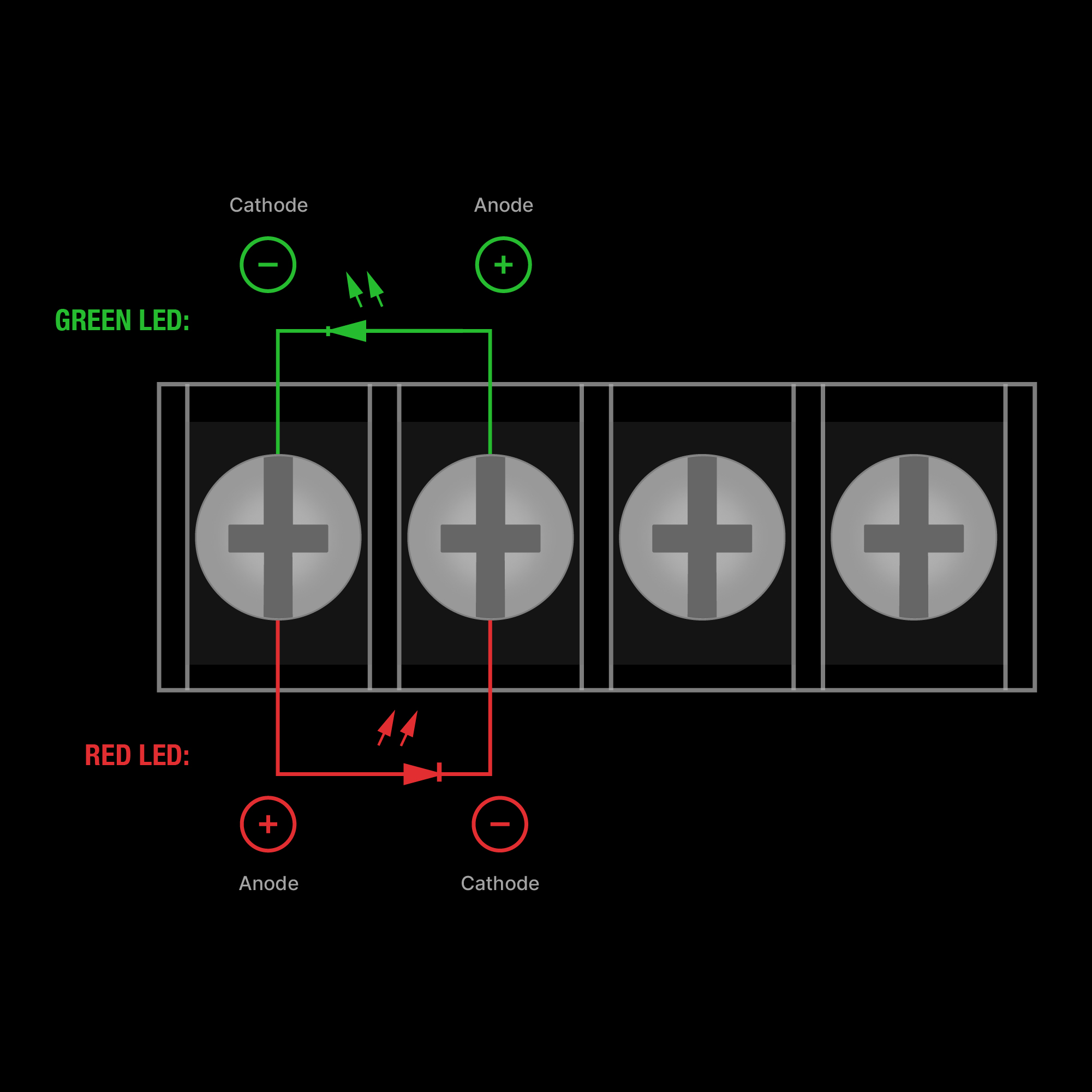
The Remote LEDs Auxiliary Port can be used to connect LEDs for easy monitoring when the charger’s interface and LEDs are not accessible. The port supports two LEDs, and it reverses the polarity between the charging identifier and the error indicator.

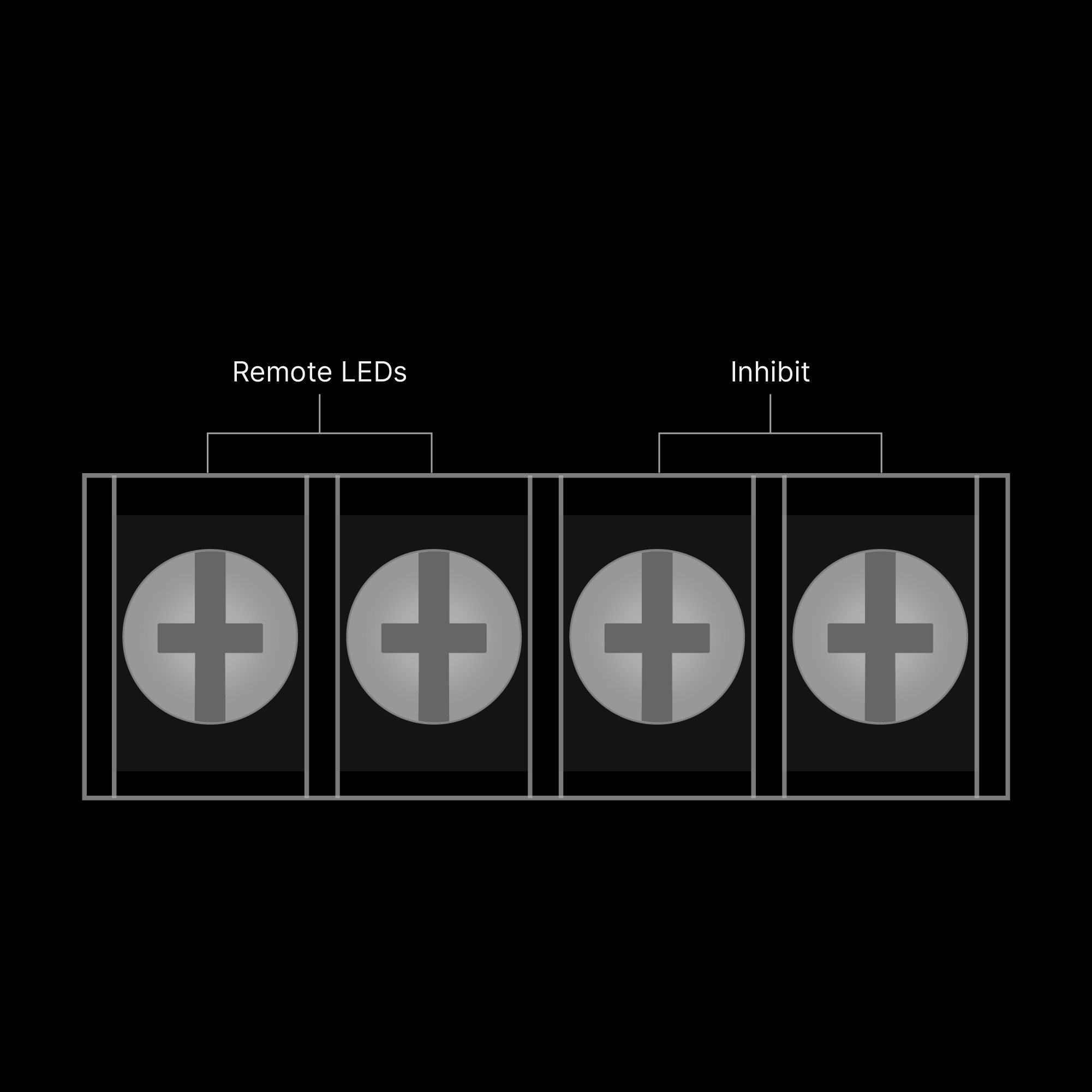
Labeled GX Auxiliary Ports:
GX Chargers give you the ability to customize with additional auxiliary functions, including adding an LED and using the inhibit feature. The port supports two LEDs, and it reverses the polarity between the charging identifier and the error indicator. The connector is designed for LEDs to directly attach (see Figure 2), with a 5V circuit and a 1K OHM resistor. As a result, the typical LED drive current is 3ma.
Understand Your Auxiliary Charging And Error LED Modes.

Charging Modes
Flash
Explanation

Blinking
Battery is charging.
Solid
Battery is fully charged.
Off
Charger is either in standby or error condition.
Flash
Explanation

Single Flash Sequence
Battery will not hold charge. Have battery checked by a professional.
Double Flash Sequence
Possible battery short. Have battery checked by a professional.
Triple Flash Sequence
Battery voltage too high for selected charge mode. Check battery and charge mode.
Quadruple Flash Sequence
Abnormal AC grid power: VAC <85V or >250V, or Frequency <45Hz or >65Hz.
Error LED Solid Red
Reverse polarity. Reverse the battery connections.
Off
Charger either charging or in standby.

Share on Facebook

Share on X

Share on Pinterest
Comment(s)
Recent Posts